About two years ago I decided that I would like to learn more about electronics to gain a better understanding of the hardware that drives my everyday work as a software engineer. I wanted a project to guide my learning and for this I started looking into DIY synthesizers, more specifically, modular synthesizers.
The idea was to design and build a range of modules for a modular synthesizer to gain an understanding of electronics. The modules in modular synthesizers generally focus on a limited scope of functionality, which are to be combined with other modules to build an overall more complex system. This allowed me to take an iterative approach to learning electronics as I could split the project into discrete modules with a particular learning goal in mind, and at the end of each step, I would have a working module that I could actually use. While designing a number of smaller modules is definitely more inefficient than one big module, having actual working hardware in my hand earlier and more frequently felt like a nice driver for motivation.
This post covers how I learned to build my first modules, including learning how to design and manufacture PCBs. I have included links to the resources that I found helpful during this project.
Goal
The goal for this part of the project was to build a simple, active module - a module that is built using active components that require power.
Possibly the simplest active module is a buffered multiple. It takes an input and duplicates it to multiple outputs.
My prior experience
My background is software engineering, mostly back-end, for the last 20 years. I did have some limited electronics knowledge, I knew the basics from school. I also have had some experience with CAD software, but not with PCB design.
I’d also played around with Arduino’s in a very limited capacity, mostly just plugging in a breakout board and copying code from examples.
Getting the basics down
Before designing my own modules, I focused on understanding the basics of electronics and the principles behind synthesizers. YouTube proved to be an invaluable resource, here are two channels that stood out:
- Look Mum No Computer: This channel offers an eclectic mix of synth related projects, from Furby organs to step-by-step building guides. His website provides schematics which were a useful resource through this process. He focuses on the “Kosmo” format, a larger version of Eurorack.
- Moritz Klein: Moritz’s videos were instrumental in building my foundation. His videos and DIY kits, developed with Erica Synths, come with in-depth documentation that guide you through building the whole circuit out piece by piece on a breadboard. I started with his VCO, dual VCA, and envelope generator modules, which were invaluable in preparing for my own designs.
Eurorack
I chose the Eurorack format for my synth because it’s the most common format for off-the-shelf modular synths, and it’s compact, perfect for someone who lives in an apartment in London! However, Eurorack has it’s quirks.
First, the small size can make designing complex modules challenging, as fitting many components into such a compact space requires careful planning. While this wasn’t an issue for my initial projects, it’s something I’ll address as I take on more ambitious designs.
Another challenge is the lack of a strict standard for power specifications. While Doepfer provides general guidelines, not all modules or schematics you’ll find online will comply. To avoid compatibility issues, I decided to adopt a consistent standard for my designs that aligns with common practices. For anyone buying modules off-the-shelf, double-checking voltage compatibility is a must.
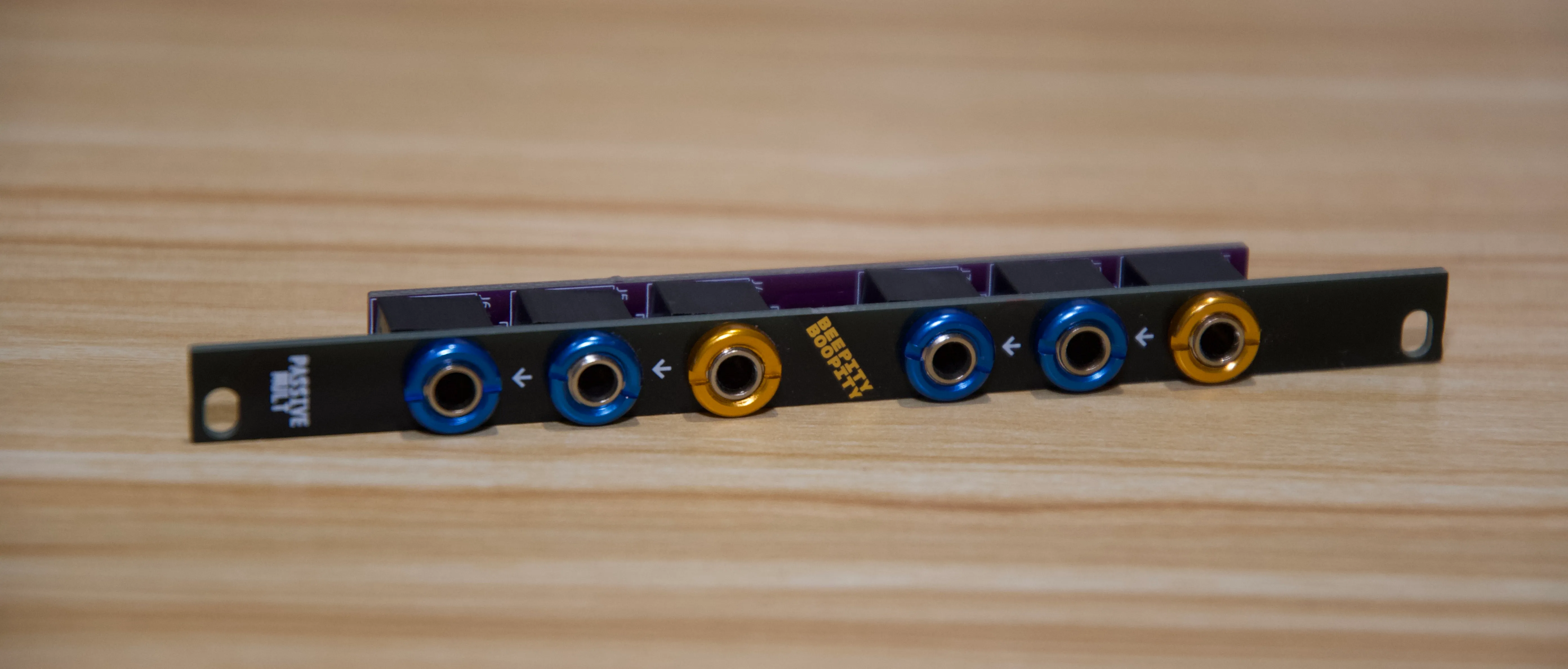
First Module - Passive Multiple

For my first project, I chose to design the simplest module possible: a passive multiple. It’s one of the simplest circuits you can build, it’s literally just a few audio jacks wired together.
This project was a perfect introduction to PCB design. It let me focus on the basics, like creating a front panel, arranging simple traces, and navigating the manufacturing process—all without the complexity of powered components. The simplicity of the design also meant fewer opportunities for errors, making it an ideal confidence booster.
For this module, I mostly followed a YouTube playlist. It uses KiCad for the design of both the PCB and the front panel, which is a pretty popular and full featured open source PCB design tool. I felt like it got me to a point where I could add some slight modifications and get PCBs actually ordered.
There were a few mistakes in this series that made it a little hard to follow, such as unclear ordering of videos. But more critically, the module would not fit in a lot of Eurorack cases. The PCB behind the front panel has fairly limited size constraints to ensure it will actually fit in the case. This was due to the number of jacks lined up vertically, meaning the PCB was around 113mm when the recommend maximum height is roughly 108mm. It’s also important to note that this maximum size will only work if the PCB is vertically centered. I’m glad I caught this before ordering my module, otherwise it would have been a pretty disappointing experience!
For the front panel, it’s a pretty common approach in DIY modular synth to use PCBs as the panel and ordering them from the same manufacturer as the boards themselves. They can cut the boards to size, drill any necessary holes, and print the design you need. And the result can be of a decent quality. There are limitations in the approach, such as a limited variety in the color of the panels, and quality can be varied across boards, but it was enough for me.
Once the module had arrived and was assembled, I was pretty happy with the result. Everything worked as expected, and I put it straight to use in my modular synth.
Learnings
- Technical:
- Basic PCB design: From schematic creation to ordering a functional board.
- Front panel design: Designing a front panel and seeing how this looked in person.
- This ended up being a really simple way to get some pretty professional looking panels manufactured. There are definitely cheaper methods, but I was happy with how this turned out.
- Process:
- Ordering PCBs: Discovered that getting PCBs manufactured is simpler and cheaper than I expected.
- Checks: Learned to double-check PCB sizes to ensure compatibility with Eurorack cases.
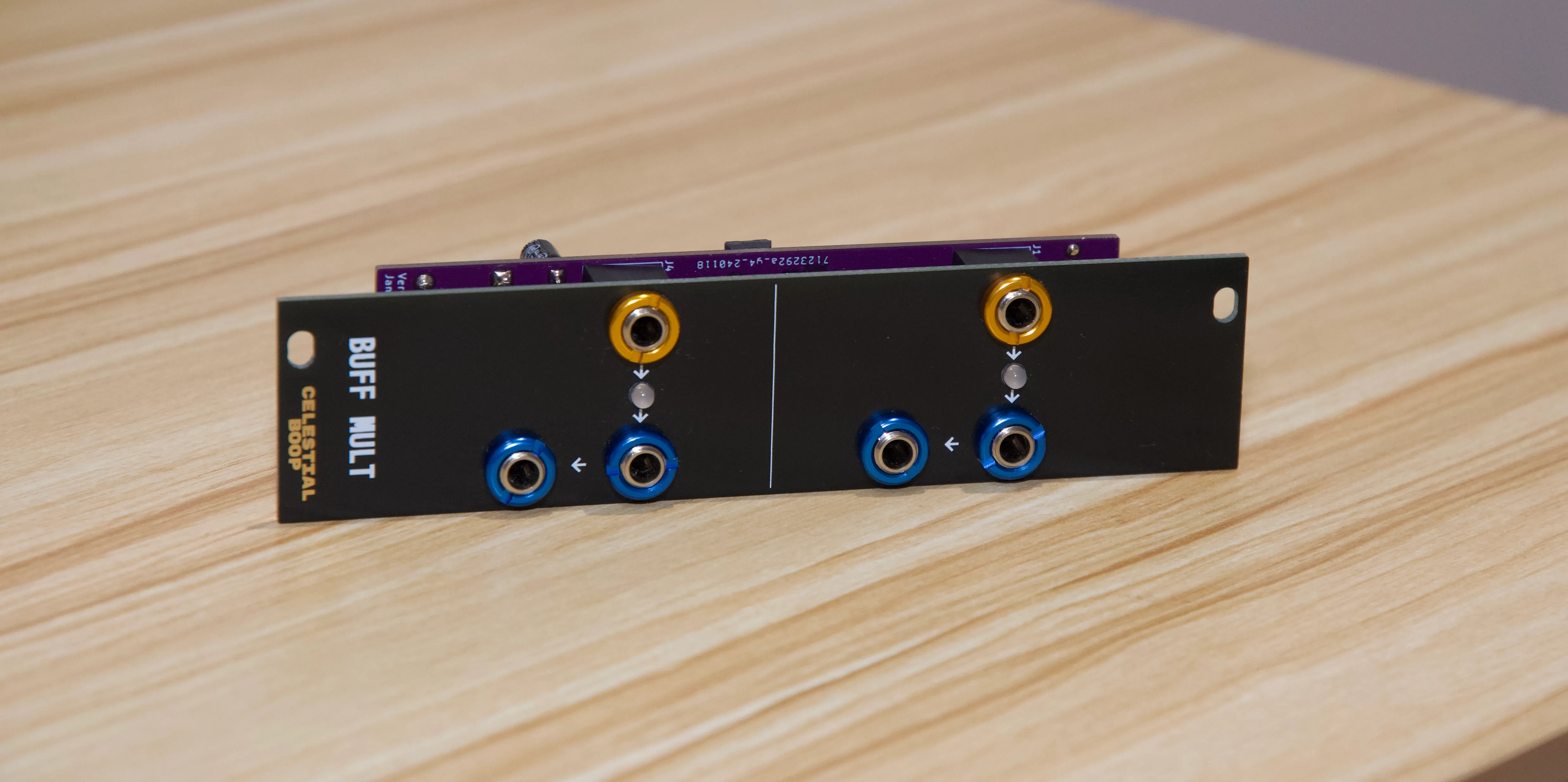
Second Module - Buffered Multiple

After the first module went so well, I figured I would jump straight into designing an active module! For this I chose a buffered multiple, similar function to the passive multiple, but the signal is “buffered” using op-amps which prevents any outputs skewing the outputs for others.
There would be a few extra steps to take into consideration with this module. First is that I would have to power it, and understand how that would work. There’s a standard Eurorack power socket I would use for this. And I needed to learn how to deliver the power to the op-amps and figure out how decoupling capacitors work.
For this, I would rely on schematics of others to understand how things should work.
There were a few particularly useful examples:
- Video from Kristian Blåsol designing a buffered multiple
- Schematic from MeeBilt of a buffered multiple
Unlike the first module, there were some mistakes that could have potentially been avoided with better checks, such as:
- Power socket was the wrong way around, this error came from part of a schematic that I was copying and I thankfully caught it before I ordered the PCB.
- I didn’t catch that one of the LEDs was incorrectly wired to the op-amp. I think this happened when I copied one of the op-amps and forgot to flip it in the schematic. Thankfully the module is still fully functional and it’s just an LED that doesn’t work.
After this module, I’ve started keeping a checklist to follow before I order each PCB. And I’m sure more mistakes will happen in the future, and I’ll add them to the checklist.
Learnings
- Technical:
- Power: Learned how to power a module and how to use decoupling capacitors.
- Circuit design: Learned how to use op-amps to buffer a signal.
- Process:
- Avoiding mistakes: I made a few mistakes that could have potentially been avoided with better checks, such as:
- Checking orientation of components after copying components on a schematic.
- Double checking reference schematics to ensure they are correct.
- Checklist: Writing a checklist to follow before I order each PCB.
- Avoiding mistakes: I made a few mistakes that could have potentially been avoided with better checks, such as:
Summary
I felt like I learnt a lot from building these two modules, they were at a level where complex electronic knowledge wasn’t required, and the various resources I found were invaluable. I think taking the iterative approach worked well, as soon as I had the first module in my hand, I was straight on with starting the next one. It was a great motivator having a physical product made, it’s not an experience I’ve had before! Software is great, but it was a nice experience building something physical.
For my next module, I’ll be designing something more complex, but I’ll still be relying on schematics of others to guide me.
Other Resources
- YouTube: How to Design a Synth Interface in KiCad
- YouTube: Creating Custom Eurorack Panels
- Website: benjiaomodular
- Variety of open-source modules, and a really useful YouTube channel
- Website: Music From Outer Space
- Huge collection of schematics